The Ultimate JOHN DEERE® Rubber Track Reference Guide
Table of Contents
I. Introduction and Track Terminology

Farming operations across the world are unique. Working closely with track tractor and combines owners, We have created an extensive line of tracks to fit virtually any application. This guide is intended to help you better understand the complete line of tracks for tractors and provide helpful recommendations for the best use of each type.
All tractor tracks are built by us using an exclusive manufacturing process that keeps each component in place, resulting in a stronger track.
To choose the best track for your operation, carefully consider your applications:
■ Cropping patterns
■ Typical field conditions, soil types and terrain
■ Implements used
■ Amount of road travel
With knowledge of your local conditions and applications, we can help you use this guide to find the best track for your operation.
I.1 Agricultural Track Terminology
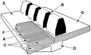
Our tracks are constructed using a combination of natural and synthetic rubber in combination with steel reinforcing plies and continuous wound main cables. The main cables give the track tension strength. The bias and reinforcement plies protect the main cables, provide internal track alignment, and further increase lateral stiffness to better distribute loads across the track width. The tread bars are designed with specific shapes, with each shape giving a distinct performance advantage in specific applications.
Positive Drive
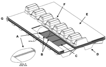
A: Main cables
B: Alignment plies
C: Reinforcement plies D: Tread bar
E: Inside (ID) surface F: Drive lug
G: Carcass
Friction Drive
A: Main cable
B: Guide lug or drive lug
C: Outer diameter (OD) bias plies (for cable protection and alignment) D: Tread bar
E: Inside diameter (ID) track surface
F: Inside diameter (ID) bias ply (for cable protection) G: Carcass
II. TRACK MACHINE OPERATIONAL GUIDELINES
II.1 New Track Break-In
Tracks should be operated in dry soil as soon as possible after new installation Track guide and drive lugs, especially on new machines, benefit from correct break-in procedures. Correct break-in through immediate introduction of the track into dry soil helps reduce the initial amount of heat generation. Track components undergo a polishing-in process during the break-in period. During this time, flash is worn from wheel edges and a smooth steel to rubber interface is developed. New rubber surfaces benefit from frequent contact with the soil, which acts as a dry lubricant, and will facilitate smooth break-in and minimize heat during break-in activities. Improper break-in may result in scuffs and poor appearance to the side of the guide or drive lugs, This will polish over once proper break-in procedures are resumed. Any significant transport distances before introduction in the field should be avoided or heat related damage to track and system components can result.
II.2 Maintain Track Alignment
Track alignment should be checked periodically (per machine operator manual instructions), especially during break-in. Alignment may change throughout the life of the machine due to track or track system component wear. Significant misalignment may result in heating and accelerated wear to one side of the guide or drive lug, as well as cause heat related damage to the midrollers and drive wheels.
The most common way to verify alignment is through use of a shim to check guide or drive lug clearance with the front midrollers by driving a fixed distance and coasting to a stop on a flat hard surface. See your machine operators manual for proper procedures for checking and adjusting alignment on your specific platform.
Temperature differential between the inner and outer surface of a guide or drive lug can also be used as a secondary step to refine the alignment, if needed. However, it is acceptable to have some temperature differential remaining once the machine passes the shim check. As long as the temperature differential is maintained at less than 20 oC (40 oF), as measured during road transport, no further alignment adjustment should be required.
II.3. Correct Operational Techniques
Tracks can pull more – so reduce loads at low speeds
Tracks deliver much less slip in high torque, low speed operations. Follow the operator’s manual guidelines and stay above the minimum speed for full load operation. Never exceed the maximum ballasted weight in order to gain more traction in lower gears.
Use proper amounts of ballast
Ballast the tractor to achieve no less than 2-5% slip under heavy pull conditions. In addition, the best track performance comes from even weight distribution along the entire track length. Correct ballast will result in reduced tread bar wear, longer rolling component life, less compaction, and improved ride and turning performance.
Maintain correct track tension
In a friction drive system, proper track tension is critical to achieve maximum tractive performance. Inadequate tension can allow more material between the track and wheels, allow track to drive wheel slip, and increase the potential for untracking.
Keep material out of the track
Track systems are designed to allow for some amounts of material to pass between the drive wheel and track. However, uncompressable objects will cause very high localized track loading, which can result in chips, chunks, and tears in the track and undercarriage components. In addition, excessive material build-up inside the undercarriage can cause the tensioning system to run out of recoil. If recoil is used up, track tearing can occur. If a tractor becomes stuck, always dig out the undercarriage and pull the machine out backwards to avoid track damage.
Use care when crossing ditches or transitions
Track machines have certain maneuvers that should be approached with care. One example is during a transition from a sloped to a flat area, especially if transitioning at a diagonal. If dynamic turning is attempted during the transition, the risk is higher for untracking to occur. Operate at low speeds, and avoid turning, to minimize the risk of untracking in these situations.
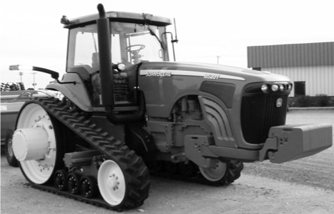
III. 8000T/8RT SERIES TRACK TRACTORS SPECIFICATIONS AND INFORMATION
General Facts
■ Produced 1997 to present
■ 220-360 HP
■ 324 in Length Track (1997-2008)
■ 354 in Length Track (2009-present)
Gauge Width
■ 60 in – 88 in Standard (1997-2008)
■ 92 in -120 in Wide (1997-2008)
■ 72 in – 120 in Standard (2009-present)
■ 112 in – 160 in Wide (2009-present)
Track System Service Information
8000T Series Alignment Torques
■ Adjusting Bolt 41 ft-lbs (55 N-m)
■ Lock Nut 120 ft-lbs (160 N-m)
8RT Series Torques
■ Alignment Adjusting Bolt 220 ft-lbs (300 N-m)
■ Alignment Lock Plate Cap Screw 95 ft-lbs (130 N-m)
Front Idler Bolts 450 ft-lbs (610 N-m)
■ Tighten bolts, retension, then retighten.
Machine Specific Notes
8000T Series
Machines may have trouble with worn bushings and difficulty in movement in the front idler adjustment mechanism. If guide lugs are worn on one side, and can’t be aligned, worn bushings or froze up alignment mechanism could be the cause.
If changing tracks, verify the front idler bushings are not worn past John Deere specifications. If they are, replace them or track alignment may not be successful.
8RT Series
Drivewheel must be positioned correctly on the axle in order for successful alignment to occur. If the alignment adjustment takes more than 3 turns off-center, then check both mid-frame and drivewheel positions for correct location.
Drivewheel must be within 1/8 in of proper position as shown in operators manual in order to successfully align the track.
III.1 8000T-8030T SERIES (324 IN CIRCUMFERENCE) TRACK SELECTION
The John Deere 8000T-8030T Series tractors offered 2 undercarriage base widths and were the first rubber track tractors offered by John Deere for the Ag market. The tracks are tensioned by a nitrogen accumulator and hydraulic cylinder. Track tension pressure should be maintained at approximately 2750 psi (19,000 kPa). This creates a track tension at approximately 12,000 lbs (5450kg). High and low pressure alarms warn the operator of potential issues. Correct track tension pressure should be maintained to avoid either overtension or track to drive wheel slippage. Refer to the Operation and Maintenance Manual (OMM) for procedures to properly maintain track tension. 8000T-8030T Models [324 in (8230 mm) Track Circumference]: 8100T 8200T 8300T 8400T 8110T 8210T 8310T 8410T 8120T 8220T 8320T 8420T 8520T 8130T 8230T 8330T 8430T 8530T
| P/N | TRACK WIDTH | CARCASS THICKNESS | GUIDE LUGS | TREAD BARS | TREAD BAR HEIGHT | TREAD BAR PITCH |
|---|---|---|---|---|---|---|
| 631-1608 | 16 in (406 mm) | 1.34 in (34 mm) | 48 | 96 | 2.6 in (66 mm) | 6.9 in (175 mm) |
| 631-1803 | 18 in (457 mm) | 1.26 in (32 mm) | 48 | 96 | 2.6 in (66 mm) | 6.9 in (175 mm) |
| 631-3040 | 30 in (762 mm) | 1.26 in (32 mm) | 48 | 96 | 2.6 in (66 mm) | 6.9 in (175 mm) |
| 631-2503 | 25 in (635 mm) | 1.26 in (32 mm) | 48 | 78 | 2.6 in (66 mm) | 8.5 in (216 mm) |
| F25AT02942 | 25 in (635 mm) | 1.26 in (32 mm) | 48 | 96 | 2.6 in (66 mm) | 6.9 in (175 mm) |
| F30AT02943 | 30 in (762 mm) | 1.26 in (32 mm) | 48 | 96 | 2.6 in (66 mm) | 6.9 in (175 mm) |
| 651-1604 | 16 in (406 mm) | 1.6 in (41 mm) | 48 | 48 (RH) | 2.6 in (66 mm) | 6.9 in (175 mm) |
| 651-1605 | 16 in (406 mm) | 1.6 in (41 mm) | 48 | 48 (LH) | 2.6 in (66 mm) | 6.9 in (175 mm) |
| 651-1804 | 18 in (457 mm) | 1.6 in (41 mm) | 48 | 96 | 2.6 in (66 mm) | 6.9 in (175 mm) |
| 651-1823 | 18 in (457 mm) | 1.53 in (39 mm) | 48 | 48 (RH) | 2.6 in (66 mm) | 6.9 in (175 mm) |
| 651-1824 | 18 in (457 mm) | 1.53 in (39 mm) | 48 | 48 (LH) | 2.6 in (66 mm) | 6.9 in (175 mm) |
| 651-2504 | 25 in (635 mm) | 1.6 in (41 mm) | 48 | 96 | 2.6 in (66 mm) | 6.9 in (175 mm) |
| 651-3039 | 30 in (762 mm) | 1.6 in (41 mm) | 48 | 96 | 2.6 in (66 mm) | 6.9 in (175 mm) |
III.2 8RT SERIES (354 IN CIRCUMFERENCE) TRACK SELECTION
The 8RT series offers an all new undercarriage design, and incorporates an air suspension system that improves ride, reduces vibration, and reduces maintenance costs.The tracks are tensioned by a nitrogen accumulator and hydraulic cylinder. Track tension pressure should be maintained at 2950 psi (20,339 kPa). This creates a track tension at approx. 16,000 lbs (7257 kg). Track tension pressure can be monitored utilizing the tractor monitor screen on most 8RT Series Tractors. High and low pressure alarms warn the operator of potential issues.
Correct track tension pressure should be maintained to avoid either overtension or track to drive wheel slippage Refer to the Operation and Maintenance Manual (OMM) for procedures to properly maintain track tension.
8RT Models [354 in (8992 mm) Track Circumference]:
8295RT 8310RT 8320RT
8335RT 8345RT 8360RT
8370RT
| P/N | TRACK WIDTH | CARCASS THICKNESS | GUIDE LUGS | TREAD BARS | TREAD BAR HEIGHT | TREAD BAR PITCH |
|---|---|---|---|---|---|---|
| F16AY02946 | 16 in (406 mm) | 1.46 in (37 mm) | 46 | 50 (RH) | 2.6 in (66 mm) | 7.30 in (185 mm) |
| F16AY02947 | 16 in (406 mm) | 1.46 in (37 mm) | 46 | 50 (LH) | 2.6 in (66 mm) | 7.30 in (185 mm) |
| F16AY03238 | 16 in (406 mm) | 1.46 in (37 mm) | 46 | 100 | 2.6 in (66 mm) | 7.30 in (185 mm) |
| F18AY02951 | 18 in (457 mm) | 1.46 in (37 mm) | 46 | 100 | 2.6 in (66 mm) | 7.30 in (185 mm) |
| F24AY03010 | 24 in (609 mm) | 1.46 in (37 mm) | 46 | 100 | 2.6 in (66 mm) | 7.30 in (185 mm) |
| F25AY03012 | 25 in (635 mm) | 1.46 in (37 mm) | 46 | 100 | 2.6 in (66 mm) | 7.30 in (185 mm) |
| F30AY03014 | 30 in (762 mm) | 1.46 in (37 mm) | 46 | 100 | 2.6 in (66 mm) | 7.30 in (185 mm) |
| F25AY02952 | 25 in (635 mm) | 1.46 in (37 mm) | 46 | 100 | 2.6 in (66 mm) | 7.30 in (185 mm) |
| F30AY02953 | 30 in (762 mm) | 1.46 in (37 mm) | 46 | 100 | 2.6 in (66 mm) | 7.30 in (185 mm) |
| E16AY02944 | 16 in (406 mm) | 1.73 in (44 mm) | 46 | 50 (RH) | 2.8 in (71 mm) | 7.30 in (185 mm) |
| E16AY02945 | 16 in (406 mm) | 1.73 in (44 mm) | 46 | 50 (LH) | 2.8 in (71 mm) | 7.30 in (185 mm) |
| E16AY03237 | 16 in (406 mm) | 1.73 in (44 mm) | 46 | 100 | 2.8 in (71 mm) | 7.30 in (185 mm) |
| E18AY02948 | 18 in (457 mm) | 1.73 in (44 mm) | 46 | 100 | 2.8 in (71 mm) | 7.30 in (185 mm) |
| E25AY03011 | 25 in (635 mm) | 1.65 in (42 mm) | 46 | 100 | 2.8 in (71 mm) | 7.30 in (185 mm) |
| E30AY03013 | 30 in (762 mm) | 1.65 in (42 mm) | 46 | 100 | 2.8 in (71 mm) | 7.30 in (185 mm) |
III.3 TRACK WIDTH vs Application Matrix
| Matrix | APPLICATION/OPERATION DESCRIPTION | 16 in (406 mm) | 18 in and 24 in (457 mm and 607 mm) | 25 in and 30 in (635 mm and 762 mm) |
|---|---|---|---|---|
| Field Conditions | Minimal ground disturbance/Berming | OK to use | OK to use | Recommended |
| Extreme cold | OK to use | OK to use | OK to use | |
| In furrow applications | OK to use | OK to use | Not recommended | |
| Short fields, applications requiring a lot of turning | OK to use | OK to use | OK to use | |
| Flat land farming, slopes up to 10% | OK to use | OK to use | OK to use | |
| Moderate side slope applications, slopes from 10 to 25% | Not recommended | OK to use | OK to use | |
| Severe side slope applications, slopes greater than 25% | Not recommended | Not recommended | OK to use | |
| Road Travel | Small amount of roading, most field and travel distances within 5 mile radius | OK to use | OK to use | OK to use |
| Moderate amount of roading, most field and travel distances between 5 and 10 mile radius | OK to use | OK to use | OK to use | |
| High amount of roading, typically travel in excess of 10 miles | Not recommended | OK to use | Recommended | |
| Applications | Primary tillage (deep ripping, chisel plow, etc.) | Not recommended | OK to use | Recommended |
| Secondary tillage (field cultivator, disk, roller, etc.) | OK to use | OK to use | OK to use | |
| Fully mounted roll over plow | Not recommended | OK to use | Recommended | |
| Row crop planter | OK to use | OK to use | OK to use | |
| Air seeder | Not recommended | OK to use | Recommended | |
| Manure tank | Not recommended | OK to use | OK to use | |
| Grain cart | Not recommended | OK to use | OK to use | |
| Tile plow | Not recommended | OK to use | OK to use | |
| Spraying | OK to use | OK to use | OK to use | |
| Hay baling | OK to use | OK to use | OK to use | |
| Stalk chopper/Brush hog | OK to use | OK to use | OK to use | |
| Vegetable bedder | OK to use | OK to use | OK to use | |
| Front Blade – Silage | Not recommended | OK to use | OK to use | |
| Forage harvester | OK to use | OK to use | OK to use | |
| Snow grooming | Not recommended | OK to use | OK to use | |
| Agricultural scraper | Not recommended | OK to use | OK to use | |
| Commercial scraper | Not recommended | Not recommended | OK to use | |
| Forestry | Not recommended | OK to use | OK to use | |
| Non-agricultural applications | Not recommended | OK to use | OK to use |
III.4 TRACK OEM / Aftermarket Cross Reference
| Models | P/N | JOHN DEERE P/N | TRACK WIDTH |
|---|---|---|---|
| 8000T Through 8030T Series | 631-1608 | R241742 | 16 in (406 mm) |
| 631-1803 | R241743 | 18 in (457 mm) | |
| 631-2509 | R241745 | 25 in (635 mm) | |
| 631-3040 / 631-3012 | R292528 / R241747 | 30 in (762 mm) | |
| F25AT02942 | R545939 | 25 in (635 mm) | |
| F30AT02943 | R545938 | 30 in (762 mm) | |
| 651-1604 (RH) | R222974 | 16 in (406 mm) | |
| 651-1605 (LH) | R222975 | 16 in (406 mm) | |
| 651-1804 | R222976 | 18 in (457 mm) | |
| 651-1823 (RH) | R312148 | 18 in (457 mm) | |
| 651-1824 (LH) | R312149 | 18 in (457 mm) | |
| 651-2504 | R241750 | 25 in (635 mm) | |
| 651-3039 / 651-3040 | R292531 / R292528 | 30 in (762 mm) | |
| 8RT Series | F16AY02946 / 631-1627 | R545853 / R266184 | 16 in (406 mm) |
| F16AY02947 / 631-1630 | R545852 / R266185 | 16 in (406 mm) | |
| F16AY03238 | NA | 16 in (406 mm) | |
| F18AY02951 / 631-1819 | R545856 / R266187 | 18 in (457 mm) | |
| F24AY03010 / 631-2401 | R545860 / R265475 | 24 in (609 mm) | |
| F25AY03012 / 631-2524 | R545861 / R272485 | 25 in (635 mm) | |
| F30AY03014 / 631-3032 | R545863 / R265476 | 30 in (762 mm) | |
| F25AY02952 | R545865 | 25 in (635 mm) | |
| F30AY02953 | R545866 | 30 in (762 mm) | |
| E16AY02944 / 651-1628 | R545855 / R266188 | 16 in (406 mm) | |
| E16AY02945 / 651-1629 | R545854 / R266189 | 16 in (406 mm) | |
| E16AY03237 | R563760 | 16 in (406 mm) | |
| E18AY02948 / 651-1820 | R545859 / R266190 | 18 in (457 mm) | |
| E25AY03011 / 651-2525 | R545862 / R265477 | 25 in (635 mm) | |
| E30AY03013 / 651-3033 | R545864 / R265478 | 30 in (762 mm) |
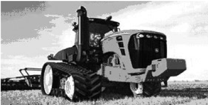
IV. 9000T/9RT SERIES TRACK TRACTORS SPECIFICATIONS AND INFORMATION
General Facts
■ Produced 1999-present
■ 375-560 HP
■ 378 in Length Track (1999-2006)
■ 387 in Length Track (2007-present)
Gauge Width
■ 106 in Gauge Width (1999-present)
Track System Service Information
9000T-9020T Series
■ No alignment adjustment available
■ Front Idler Bolts 450 ft-lbs (610 N-m)
■ Tighten bolts once before removal from stands, then 2nd time after retensioning
9030T/9RT Series
■ Alignment Lock Plate Cap Screw 95 ft-lbs (130 N-m)
■ Alignment Adjusting Bolt 220 ft-lbs (300 N-m)
■ Front Idler Bolts 790 ft-lbs (1070 N-m)
■ Drivewheel/Midroller Bolts 330 ft-lbs (450 N-m)
■ Tighten bolts once before removal from stands, then 2nd time after re-tensioning
Machine Specific Notes
9000T-9020T Series
This machine does not have track alignment adjustment. Tracks that display misalignment after installation may show some break-in scuffing. However, large temperature differences between inboard and outboard side of the guide lugs are not normal and should be investigated:
■ Check front idlers for equal circumference and possibly swap if not the same from inside to outside.
■ Check drive wheel wear. Uneven drive wheel wear can cause tracks to move towards the drive wheel with the least wear.
■ If both tracks are running in or both are running out, it may help to swap the tracks side to side to try and equalize the wear and possible better center the tracks.
■ If only 1 track is out of alignment, inspect that frame and spindle for signs of being bent.
If significant misalignment remains after these checks, have customer contact John Deere dealer and open a DTAC case concerning the track misalignment. Deere has procedures and methods to check further into the issue.
9030T-9RT Series
This machine has track alignment adjustment. Check and adjust this periodically, and always when replacing or changing tracks.
IV.1 9000T-9020T SERIES (378 IN CIRCUMFERENCE) TRACK SELECTION
Every operation demands efficiency and reliability. In order to balance track life, flotation and compaction, we offer a range of tracks to customize your tractor to your operation.
The tracks are tensioned by a nitrogen accumulator and hydraulic cylinder. Track tension pressure should be maintained at 2950 psi (20,339 kPa). This creates a track tension of approximately 22,000 lbs (10,000kg). High and low pressure alarms warn the operator of potential issues.
Correct track tension pressure should be maintained to avoid either overtension or track to drive wheel slippage. Reference the tractor’s Operation and Maintenance Manual (OMM) for procedures to properly maintain track tension.
9000T-9020T Models
[378 in (9601 mm) Track Circumference]:
9300T 9400T
9320T 9420T 9520T 9620T
| P/N | TRACK WIDTH | CARCASS THICKNESS | GUIDE LUGS | TREAD BARS | TREAD BAR HEIGHT | TREAD BAR PITCH |
|---|---|---|---|---|---|---|
| 633-3019 | 30 in (762 mm) | 1.45 in (37 mm) | 54 | 92 | 2.8 in (71 mm) | 8.4 in (213 mm) |
| 633-3606 | 36 in (914 mm) | 1.45 in (37 mm) | 54 | 92 | 2.8 in (71 mm) | 8.4 in (213 mm) |
| 653-3010 | 30 in (762 mm) | 1.6 in (41 mm) | 54 | 92 | 2.9 in (74 mm) | 8.4 in (213 mm) |
| 653-3601 | 36 in (914 mm) | 1.6 in (41 mm) | 54 | 92 | 2.9 in (74 mm) | 8.4 in (213 mm) |
IV.2 9030T-9RT SERIES (387 IN CIRCUMFERENCE) TRACK SELECTION
The 9030T-9RT series offers an all new undercarriage design, and incorporates an air suspension system that improves ride, reduces vibration, and reduces maintenance costs.
The tracks are tensioned by a nitrogen accumulator and hydraulic cylinder. Track tension pressure should be maintained at 2950 psi (20,339 kPa). This creates a track tension of approximately 26,000 lbs (11,800 kg). Track tension pressure can be monitored utilizing the tractor monitor screen on most 9030T/9RT Series Tractors. High and low pressure alarms warn the operator of potential issues.
Correct track tension pressure should be maintained to reduce damage to the tracks. Reference the tractor’s Operation and Maintenance Manual (OMM) for procedures to properly maintain track tension.
9030T-9RT Models [387 in (9830 mm) Track Circumference]:
9430T 9530T 9630T
9460RT 9470RT 9510RT
9520RT 9560RT 9570RT
9460RT
Scraper Special 9470RT
Scraper special 9510RT
Scraper Special
9520RT
Scraper special 9560RT
Scraper Special 9570RT
Scraper special
| P/N | TRACK WIDTH | CARCASS THICKNESS | GUIDE LUGS | TREAD BARS | TREAD BAR HEIGHT | TREAD BAR PITCH |
|---|---|---|---|---|---|---|
| F30AV03020 | 30 in (762 mm) | 1.46 in (37 mm) | 50 | 88 | 2.6 in (66 mm) | 9.0 in (228 mm) |
| F36AV03022 | 36 in (914 mm) | 1.46 in (37 mm) | 50 | 88 | 2.6 in (66 mm) | 9.0 in (228 mm) |
| F30AV02955 | 30 in (762 mm) | 1.46 in (37 mm) | 50 | 88 | 2.6 in (66 mm) | 9.0 in (228 mm) |
| E30AV03019 | 30 in (762 mm) | 1.73 in (44 mm) | 50 | 88 | 2.9 in (74 mm) | 9.0 in (228 mm) |
| E36AV03021 | 36 in (914 mm) | 1.73 in (44 mm) | 50 | 88 | 2.9 in (74 mm) | 9.0 in (228 mm) |
| E30AV02954 | 30 in (762 mm) | 1.73 in (44 mm) | 50 | 88 | 2.3 in (58 mm) | 9.0 in (228 mm) |
V. 8RX SERIES TRACK SELECTION SPECIFICATIONS AND INFORMATION
The 8RX series offers a wide range of track and axle configurations, tread spacing options and belt widths. Axle tread spacing can be set at 76″ (193cm), 80″ (203.2cm), 88″ (223.5cm), or 120″
(304.8cm) gauge widths.
General Facts
■ Produced 2020-up
■ 310-410 HP
■ 210″ Track length, Front
■ 252″ Track length, Rear
Gauge Width
■ 76″ (193cm)
■ 80″ (203.2cm)
■ 88″ (223.5cm)
■ 120″ (304.8cm)
Track System Service Information
■ Alignment lock plate cap screws 95-ft lbs (130 N-m)
■ Alignment adjustment bolt 220-ft lbs (300 N-m)
■ Idler bolts 360-ft lbs (490 N-m)
■ Midroller Bolts 235-ft lbs (320 N-m)
Machine Specific Notes
Material build-up on the drive sprocket, and track carcass anti-vibration rollers can be more severe in applications with damp soil or sticky crop / plant residue. The 8RX series is equipped with drive wheel and rear tension roller scrapers which must be adjusted to a 1/8 in (3 mm) uniform gap to minimize material build-up and help prevent internal track carcass damage.
The tracks are tensioned by a nitrogen accumulator and hydraulic cylinder. Track tension pressure should be maintained at 2950 psi (20,339 kPa) which creates a track tension of approximately 16,000 lbs (7,270 kg). Reference the tractor’s Operation and Maintenance Manual (OMM) for procedures to properly maintain track tension.
The 8RX series also has speed restrictions that depend on laden weight and travel duration. Track damage can result if these recommendations are not followed closely. Refer to the tractor’s Operation and Maintenance Manual (OMM) for more information.
8RX Series Tractor Models
8310RX 8340RX 8370RX 8410RX
| P/N | TRACK WIDTH | CARCASS THICKNESS | DRIVE LUGS | TREAD BARS | TREAD BAR HEIGHT | TREAD BAR PITCH |
|---|---|---|---|---|---|---|
| F16CD03572 | 16 in (406 mm) | 1.28 in (32.5 mm) | 35 | 70 | 1.1 in (30 mm) | 6.0 in (152 mm) |
| F18CD03570 | 18 in (457 mm) | 1.28 in (32.5 mm) | 35 | 70 | 1.6 in (41 mm) | 6.0 in (152 mm) |
| F24CD03574 | 24 in (610 mm) | 1.28 in (32.5 mm) | 35 | 70 | 1.6 in (41 mm) | 6.0 in (152 mm) |
| F16CA03571 | 16 in (406 mm) | 1.28 in (32.5 mm) | 42 | 84 | 1.1 in (30 mm) | 6.0 in (152 mm) |
| F18CA03569 | 18 in (457 mm) | 1.28 in (32.5 mm) | 42 | 84 | 1.6 in (41 mm) | 6.0 in (152 mm) |
| F24CA03573 | 24 in (610 mm) | 1.28 in (32.5 mm) | 42 | 84 | 1.6 in (41 mm) | 6.0 in (152 mm) |
| F30CA03717 | 30 in (762 mm) | 1.28 in (32.5 mm) | 42 | 84 | 1.6 in (41 mm) | 6.0 in (152 mm) |
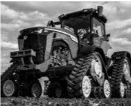
VI. 9RX WIDE SERIES (270 IN CIRCUMFERENCE) TRACK SELECTION SPECIFICATIONS AND INFORMATION
The 9RX Wide Series offers an all new 4 track positive drive under- carriage design
General Facts
■ Produced 2016-up
■ 470-640 HP
■ 270 in length track
Gauge Width
■ 87 in gauge width (221.8 cm)
■ 120 in gauge width (304.8 cm) (MY2019-up)
Track System Service Information
■ Alignment lock plate cap screw 95 ft-lbs (130 N-m)
■ Alignment adjusting bolt 220 ft-lbs (300 N-m)
■ Idler bolts 790 ft-lbs (1070 N-m)
■ Midroller (wide) bolts 330 ft-lbs (450 N-m)
Machine Specific Notes
Material build-up on the drive sprocket can be more frequent in application with damp soil or sticky crop/plant residue. The 9RX wide series is equipped with drive wheel scrapers, which must be adjusted to 1/8 in (3 mm) uniform gap, to minimize material build-up and help prevent internal track carcass damage.
The tracks are tensioned by a nitrogen accumulator and hydraulic cylinder. Track tension pressure should be maintained at 2900 psi (20,000 kPa). This creates a track tension of approximately 18,000 lbs (8,160 kg). Track tension pressure can be monitored utilizing the tractor monitor screen on earlier 9RX Series Tractors.
Correct track tension pressure should be maintained to reduce damage to the tracks. Reference the tractor’s Operation and Maintenance Manual (OMM) for procedures to properly maintain track tension.
9RX Wide Series Models [270 in (6832 mm) Track Length]:
9470RX 9490RX 9520RX
9540RX 9570RX 9590RX
9620RX 9640RX
9470RX
Scraper Special 9490RX
Scraper Special 9520RX
Scraper Special
9540RX
Scraper Special 9570RX
Scraper Special 9590RX
Scraper Special
| P/N | TRACK WIDTH | CARCASS THICKNESS | DRIVE LUGS | TREAD BARS | TREAD BAR HEIGHT | TREAD BAR PITCH |
|---|---|---|---|---|---|---|
| B30BH03053 | 30 in (762 mm) | 1.37 in (35 mm) | 45 | 90 | 2.0 in (50 mm) | 6.0 in (152 mm) |
| B36BH03047 | 36 in (914 mm) | 1.37 in (35 mm) | 45 | 90 | 2.0 in (50 mm) | 6.0 in (152 mm) |
| E30BH02877 | 30 in (762 mm) | 1.37 in (35 mm) | 45 | 90 | 2.0 in (50 mm) | 6.0 in (152 mm) |
| E36BH02897 | 36 in (914 mm) | 1.37 in (35 mm) | 45 | 90 | 2.0 in (50 mm) | 6.0 in (152 mm) |
| E30BH03054 | 30 in (762 mm) | 1.37 in (35 mm) | 45 | 90 | 1.6 in (40 mm) | 6.0 in (152 mm) |
VII. 9RX NARROW SERIES (270 IN CIRCUMFERENCE) TRACK SELECTION SPECIFICATIONS AND INFORMATION
The 9RX Narrow Series Tractors are also equipped with designed narrow undercarriages which are ideal for the 22-inch, 30-inch, and 40-inch row-crop applications.
General Facts
■ Produced 2017-up
■ 420-540 HP
■ 270 in length track
Gauge Width
■ 80 inches (203.20 cm)
■ 88 inches (60.96 cm)
■ 120 inches (304.80 cm)
Track System Service Information
■ Alignment lock plate cap screw 95 ft-lbs (130 N-m)
■ Alignment adjusting bolt 220 ft-lbs (300 N-m)
■ Idler bolts 790 ft-lbs (1070 N-m)
■ Midroller bolts (narrow) 236 ft-lbs (320 N-m)
Machine Specific Notes
Material build-up on the drive sprocket can be more frequent in application with damp soil or sticky crop/ plant residue. The 9RX series is equipped with drive wheel scrapers, which must be adjusted to 1/8 in (3 mm) uniform gap, to minimize material build-up and help prevent internal track carcass damage.
The tracks are tensioned by a nitrogen accumulator and hydraulic cylinder. Track tension pressure should be maintained at 2900 psi (20,000 kPa). This creates a track tension of approximately 18,000 lbs (8,160 kg). Track tension pressure can be monitored utilizing the tractor monitor screen on earlier 9RX Series Tractors. Correct track tension pressure should be maintained to reduce damage to the tracks. Reference the tractor’s Operation and Maintenance Manual (OMM) for procedures to properly maintain track tension.
The 9RX narrow series has speed restrictions, that depend on laden weight and travel duration. Track damage can result if these recommendations are not followed. Refer to your tractor operators manual for more information.
9RX Narrow Series Models [270 in (6832 mm) Track Length]:
9420RX 9470RX 9490RX
9520RX 9540RX
| P/N | TRACK WIDTH | CARCASS THICKNESS | DRIVE LUGS | TREAD BARS | TREAD BAR HEIGHT | TREAD BAR PITCH |
|---|---|---|---|---|---|---|
| E18BT03106 | 18 in (45.72 cm) | 1.37 in (35 mm) | 45 | 90 | 1.6 in (40 mm) | 6.0 in (152 mm) |
| E24BT03107 | 24 in (60.96 cm) | 1.37 in (35 mm) | 45 | 90 | 1.6 in (40 mm) | 6.0 in (152 mm) |
VIII. 9RX HIGH HORSEPOWER SERIES (282 IN CIRCUMFERENCE) TRACK SELECTION SPECIFICATIONS AND INFORMATION
The 9RX High Horsepower Series offers an All new 4 track positive drive undercarriage design.
General Facts
■ Produced 2024-up
■ 710-830 HP
■ 282 in length track
Gauge Width
■ 88 in gauge width (223.5 cm) (for 30 in tracks only)
■ 120 in gauge width (304.8 cm)
Track System Service Information
■ Alignment lock plate cap screw 95 ft-lbs (130 N-m)
■ Alignment adjusting bolt 220 ft-lbs (300 N-m)
■ Idler bolts 590 ft-lbs (800 N-m)
■ Midroller bolts 330 ft-lbs (450 N-m)
Machine Specific Notes
Material build-up on the drive sprocket can be more frequent in applications with damp soil or sticky crop/plant residue. The 9RX High Horsepower series is equipped with drive wheel scrapers, which must be maintained at 1/8 in (3 mm) uniform gap, to minimize material build-up and help reduce internal track carcass damage.
The tracks are tensioned by a nitrogen accumulator and hydraulic cylinder. Track tension pressure should be maintained at 2950 psi (20,339 kPa). This creates a track tension of approximately 23,000 lbs (10,430 kg).
Correct track tension pressure should be maintained to reduce damage to the tracks. Reference the tractor’s Operation and Maintenance Manual (OMM) for procedures to properly maintain track tension.
9RX HHP Series Models [282 in (7163 mm) Track Length]:
9710RX 9770RX 9830RX
9710RX Scraper Special 9770RX Scraper Special
| P/N | TRACK WIDTH | CARCASS THICKNESS | DRIVE LUGS | TREAD BARS | TREAD BAR HEIGHT | TREAD BAR PITCH |
|---|---|---|---|---|---|---|
| B30CN03725 | 30 in (762 mm) | 1.37 in (35 mm) | 47 | 94 | 1.6 in (40 mm) | 6.0 in (152 mm) |
| B36CN03726 | 36 in (914 mm) | 1.37 in (35 mm) | 47 | 94 | 1.6 in (40 mm) | 6.0 in (152 mm) |
| E30CN03612 | 30 in (762 mm) | 1.37 in (35 mm) | 47 | 94 | 2.0 in (50 mm) | 6.0 in (152 mm) |
| E36CN03626 | 36 in (914 mm) | 1.37 in (35 mm) | 47 | 94 | 2.0 in (50 mm) | 6.0 in (152 mm) |
| E30CN03630 | 30 in (762 mm) | 1.37 in (35 mm) | 47 | 94 | 1.6 in (40 mm) | 6.0 in (152 mm) |
VIII.1 TRACK WIDTH vs Application Matrix
| Matrix | APPLICATION/OPERATION DESCRIPTION | 18 in (457 mm) | 24 in (610 mm) | 30 in (762 mm) | 36 in (914 mm) |
|---|---|---|---|---|---|
| Field Conditions | Minimal ground disturbance/Berming | OK to use | OK to use | OK to use | Recommended |
| Extreme cold | OK to use | OK to use | OK to use | OK to use | |
| In furrow applications | Not recommended | Not recommended | Not recommended | Not recommended | |
| Short fields, applications requiring a lot of turning | OK to use | OK to use | OK to use | OK to use | |
| Flat land farming, slopes up to 10% | OK to use | OK to use | OK to use | OK to use | |
| Moderate side slope applications, slopes from 10 to 25% | OK to use | OK to use | OK to use | OK to use | |
| Slopes greater than 25% | Not recommended | OK to use | OK to use | OK to use | |
| Road Travel | Small amount of roading, most field and travel distances within 5 mile radius | OK to use | OK to use | OK to use | OK to use |
| Moderate amount of roading, most field and travel distances between 5 and 10 mile radius | OK to use | OK to use | OK to use | OK to use | |
| High amount of roading, typically travel in excess of 10 miles | OK to use | OK to use | OK to use | OK to use | |
| Applications | Primary tillage (deep ripping, chisel plow, etc.) | Not recommended | Not recommended | OK to use | OK to use |
| Secondary tillage (field cultivator, disk, roller, etc.) | OK to use | OK to use | OK to use | OK to use | |
| Fully mounted roll over plow | Not recommended | Not recommended | OK to use | OK to use | |
| Row crop planter | OK to use | OK to use | OK to use | OK to use | |
| Air seeder | OK to use | OK to use | OK to use | OK to use | |
| Manure tank | OK to use | OK to use | OK to use | OK to use | |
| Grain cart | OK to use | OK to use | OK to use | OK to use | |
| Tile plow | Not recommended | Not recommended | OK to use | OK to use | |
| Spraying | OK to use | OK to use | OK to use | OK to use | |
| Hay baling | OK to use | OK to use | OK to use | OK to use | |
| Stalk chopper/Brush hog | OK to use | OK to use | OK to use | OK to use | |
| Vegetable bedder | OK to use | OK to use | OK to use | OK to use | |
| Front Blade – Silage | OK to use | OK to use | OK to use | OK to use | |
| Forage harvester | OK to use | OK to use | OK to use | OK to use | |
| Snow grooming | OK to use | Not recommended | OK to use | OK to use | |
| Agricultural scraper | Not recommended | Not recommended | OK to use | Not recommended | |
| Commercial scraper | Do not use | Do not use | OK to use | Not recommended | |
| Forestry | OK to use | OK to use | OK to use | OK to use | |
| Non-agricultural applications | Do not use | Do not use | OK to use | OK to use |
VIII.2 TRACK OEM / Aftermarket Cross Reference
| Models | P/N | JOHN DEERE P/N | TRACK WIDTH |
|---|---|---|---|
| 9000T-9020T Series | 633-3019 | R257977 | 30 in |
| 653-3010 | R241748 | 30 in | |
| 633-3606 | R257978 | 36 in | |
| 653-3601 | R241749 | 36 in | |
| 9030T-9RT Series | F30AV03020 / 633-3022 | R545867 / R242791 | 30 in |
| F36AV03022 / 633-3609 | R545870 / R242792 | 36 in | |
| F30AV02955 | R545872 | 30 in | |
| E30AV03019 / 653-3021 | R545868 / R242793 | 30 in | |
| E36AV03021 / 653-3608 | R545871 / R242794 | 36 in | |
| E30AV02954 / 693-3041 | R545869 / R292524 | 30 in | |
| 8RX Series | F16CD03572 | TR120910 | 16 in |
| F18CD03570 | R571655 | 18 in | |
| F24CD03574 | R571656 | 24 in | |
| F16CA03571 | TR120911 | 16 in | |
| F18CA03569 | R571658 | 18 in | |
| F24CA03573 | R571659 | 24 in | |
| F30CA03717 | TR129219 | 30 in | |
| 9RX Series | E18BT03106 | R565017 | 18 in |
| E24BT03107 | R565018 | 24 in | |
| B30BH03053 | R550588 | 30 in | |
| B36BH03047 | R550228 | 36 in | |
| E30BH02877 | R554229 | 30 in | |
| E36BH02897 | R554230 | 36 in | |
| E30BH03054 | R550589 | 30 in | |
| 9RX High Horsepower Series | B30CN03725 | TR134902 | 30 in |
| B36CN03726 | TR134903 | 36 in | |
| E30CN03612 | TR134506 | 30 in | |
| E36CN03626 | TR134507 | 36 in | |
| E30CN03630 | TR119528 | 30 in |
IX. RUBBER TRACK REPAIR AND REPLACEMENT
IX.1 TRACK REPAIR AND REPLACEMENT
For longest life, tracks should be repaired when:
■ Cables are exposed in the carcass – Cables loose
or protruding from the carcass should be trimmed to prevent damage to other components.
■ Guide lugs are missing – Bolt-on guide lug kits are available
■ Loose tread bar – Loose portion of the tread bar should be trimmed to prevent damage to other components.
IX.2 Track Replacement Criteria
For best performance, tracks should be replaced when:
■ Tread bar height is less than 0.5 in (12 mm)
■ Track to ground slippage consistently exceeds 10%
■ Several (more than 3) tread bars are missing in a row
■ Multiple (more than 5) guide lugs are missing consecutively
■ 1 or more drive lugs are missing
■ Guide lugs have excessive wear (50% of guide lugs is worn)
■ De-tracking occurs due to worn or missing guide lugs
■ The main cables have torn in the wheel path (Tear across the width of the carcass)
■ Cables are showing on the inside surface of the track
■ Drive wheel to track slippage is excessive due to missing ID rubber or rubber surface is glazed/hardened from drive wheels slipping.
XI. Conclusion - Partner with the Experts for Your John Deere Tracks
Navigating the world of John Deere rubber tracks can be complex, but with this ultimate guide, you’re now better prepared to make an informed decision. Choosing the correct tracks is a critical investment in your equipment’s efficiency and longevity.
At Nissitrac, we don’t just sell tracks; we provide solutions. Our team of experts is passionate about helping you find the precise rubber tracks tailored to your John Deere model and specific operational needs. We understand the demands of your work and are dedicated to supplying tracks that can handle the toughest conditions.
Let us help you find the perfect match: Discuss Your Needs with a Nissitrac Specialist Now.
Make the right choice for your John Deere. Choose Nissitrac for unparalleled expertise, quality products, and dedicated customer support.
Comments

Related Blogs
Find the latest updates and common knowledge in rubber track industry.